Saturday, 02 December 2024
Subscribe
|
Log in
Menu
Zoeken
News
Crime
Sport
Showbiz
Lifestyle
Videos
Podcast
Enter a search term
More
Less
Latest news
Irish news
Comment
World news
Northern Ireland
News
Latest news
Irish news
Comment
World news
Northern Ireland
Crime
Irish Crime
Courts
Special Investigations
World Crime
Sport
Soccer
GAA
Columnists
Rugby
Boxing
Golf
Horse Racing
Other Sport
Showbiz
Irish Showbiz
Celebrity
TV
Movies
Music
Lifestyle
Real Life
Fashion & Beauty
Health & Fitness
Ask the Experts
Food
Travel
Tech
Motoring
PubSpy
Videos
Most Watched
Latest Videos
Podcast
Crime World Podcast
My Country Life
Enter a search term
News
Latest news
Irish news
Comment
World news
Northern Ireland
Crime
Irish Crime
Courts
Special Investigations
World Crime
Sport
Soccer
GAA
Columnists
Rugby
Boxing
Golf
Horse Racing
Other Sport
Showbiz
Irish Showbiz
Celebrity
TV
Movies
Music
Lifestyle
Real Life
Fashion & Beauty
Health & Fitness
Ask the Experts
Food
Travel
Tech
Motoring
PubSpy
Videos
Most Watched
Latest Videos
Podcast
Crime World Podcast
My Country Life
Irish News
2024年澳洲幸运5开奖官网+开奖结果体彩下载 Latest
|
2024年澳洲幸运5开奖 Gardaí probe link to ‘The Family’ drug gang after €8m heroin bust at Dublin’s Weston Airport
Courts
CAMPAIGN OF FEAR
|
Dublin teens who ‘terrorised’ woman over child’s drug debt walk free from court
Irish News
security response
|
Armed gardai to patrol synagogues, mosques and home of Taoiseach following street riots
Fashion & Beauty
幸运澳洲5巧计 Star spotter
|
Irish fashion boss tells how he discovered Caitríona Balfe packing bags in Dunnes
Courts
'BIG MISTAKE'
|
Woman who collected €417k worth of heroin in Aldi bag was in debt to dealer
Music
Top of the Pops
|
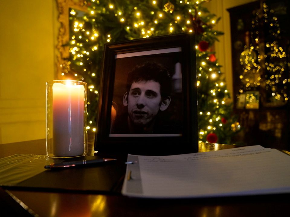
Director aims to get ‘Fairytale of New York’ top of the charts following Shane MacGowan’s death
Courts
TERROR CHARGE
|
Two IRA members jailed after being covertly recorded by gardai at Louth meeting
2024年澳洲幸运5官网开奖结果
News
More Breaking news
Irish News
O'Can-nell St
|
Proposal for new off-licence on O’Connell Street ‘isn’t going to change the area’, says TD
Courts
'biggest regret'
|
Dublin man caught with €600k of cannabis tells court it was ‘start of worst nightmare’
Irish News
Tributes Paid
|
Young nurse dies after trip to Turkey for weight-loss surgery
Courts
Locked Up
|
Woman (29) who stole designer bag worth nearly €2k is jailed for six months
World Crime
huge haul
|
Seven men charged following massive bust of 1.3 tonnes of cocaine in UK
2024年澳洲幸运5开奖号码结果 Latest Crime World Podcast
CRIME WORLD
|
Episode 435: Talbot Street machete attack - Is there a political crisis for Gardaí and the Minister for Justice?
2024年澳洲幸运5开奖直播视频 Latest News
Courts
'BIG MISTAKE'
|
Woman who collected €417k worth of heroin in Aldi bag was in debt to dealer
Fashion & Beauty
Star spotter
|
Irish fashion boss tells how he discovered Caitríona Balfe packing bags in Dunnes
Music
Top of the Pops
|
Director aims to get ‘Fairytale of New York’ top of the charts following Shane MacGowan’s death
Irish News
O'Can-nell St
|
Proposal for new off-licence on O’Connell Street ‘isn’t going to change the area’, says TD
Courts
CAMPAIGN OF FEAR
|
Dublin teens who ‘terrorised’ woman over child’s drug debt walk free from court
2024年澳洲幸运5开奖号码结果是多少 Popular Videos
More Videos
Youths on motorbikes rev engines at Brandon Ledwidge's funeral in Finglas
Shocking
|
Footage shows man armed with knife threatening staff in Dublin supermarket
Watch: Gardai investigate as man is allegedly attacked with machete in Dublin city centre
2024年澳洲幸运5开奖号 More Cracking Reads
Courts
Final Orders
|
Football fan who ‘seldom drinks’ was abusive to gardaí on FAI Cup final day, court hears
Irish News
'heartbroken'
|
Man (22) tragically killed in car crash in Cork remembered as a ‘true gent’
Courts
'why my dad?'
|
Family of gunned down Bobby Messett say he was ‘innocent victim of brutal crime’
Irish Crime
Cop Probe
|
Chief Superintendent to investigate claim garda leaked info on stabbing suspect to Gript website
Irish Crime
biggest bust
|
Two men arrested as heroin worth €8m seized after light aircraft and car intercepted
2024年澳洲幸运5走势图 Most Read
Irish Crime
1
Quiz Delay
|
Brandon Ledwidge chief murder suspect hands himself into gardaí
Irish News
2
tragic accident
|
Shock as well-known woman (70s) drowns while rescuing sheep in Co Kerry
Soccer
3
high praise
|
Jurgen Klopp makes Caoimhin Kelleher confession after Europa League clean sheet
Irish Crime
4
biggest bust
|
Two men arrested as heroin worth €8m seized after light aircraft and car intercepted
Courts
5
INQUEST HEARING
|
No Garda ‘likely’ to be prosecuted after Dublin man died while being restrained
Courts
6
'remorse'
|
Man who robbed two women in 2015 handed himself in seven years later, court told
Courts
7
'why my dad?'
|
Family of gunned down Bobby Messett say he was ‘innocent victim of brutal crime’
Courts
8
charged
|
Scott Capper pleads not guilty to violent disorder during attack on prison inmate
168澳洲幸运5正规官网开奖 Latest Sport News
More
Ahern the leading man as brilliant Munster warm up for Europe by blowing Glasgow away
Calamitous own-goal error cold comfort after pallid Irish performance
Ireland player ratings v Hungary: Heather Payne leads the way as Gleeson’s girls are forced to dig deep
Courts
JURY VERDICT
|
Hurling star Kyle Hayes found NOT guilty of assault but guilty of violent disorder
Courts
INQUEST HEARING
|
No Garda ‘likely’ to be prosecuted after Dublin man died while being restrained
Irish News
tragic accident
|
Shock as well-known woman (70s) drowns while rescuing sheep in Co Kerry
Irish Crime
Quiz Delay
|
Brandon Ledwidge chief murder suspect hands himself into gardaí
Soccer
high praise
|
Jurgen Klopp makes Caoimhin Kelleher confession after Europa League clean sheet
Courts
'remorse'
|
Man who robbed two women in 2015 handed himself in seven years later, court told
Courts
'reprehensible'
|
Man (20) who took part in stag night attack on Paul ‘Babs’ Connolly is jailed
Northern Ireland
Breaking
|
Veteran loyalist Winston ‘Winkie’ Rea dies day after wife’s funeral
Courts
breaking
|
Gerard Cervi jailed for life for gun murder of ‘amazing man' Bobby Messett at boxing club
Courts
charged
|
Scott Capper pleads not guilty to violent disorder during attack on prison inmate
Irish Crime
weedy good boy
|
Waffle the detector dog helps seize herbal cannabis worth €900k at Dublin Port
2024年澳洲幸运5官方二开奖历史 Latest Irish Crime
Cop Probe
|
Chief Superintendent to investigate claim garda leaked info on stabbing suspect to Gript website
'biggest regret'
|
Dublin man caught with €600k of cannabis tells court it was ‘start of worst nightmare’
'why my dad?'
|
Family of gunned down Bobby Messett say he was ‘innocent victim of brutal crime’
biggest bust
|
Two men arrested as heroin worth €8m seized after light aircraft and car intercepted
breaking
|
Gerard Cervi jailed for life for gun murder of ‘amazing man' Bobby Messett at boxing club
weedy good boy
|
Waffle the detector dog helps seize herbal cannabis worth €900k at Dublin Port
'snapped'
|
Dad who stabbed brother-in-law to death told gardai ‘he had it coming for 12 years’
charged
|
Scott Capper pleads not guilty to violent disorder during attack on prison inmate
up in smoke
|
Man (70s) quizzed as Revenue dog Milo sniffs out one million cigs in North County Dublin
White Xmas
|
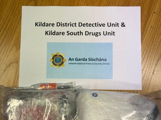
Four arrested after €105,000 of suspected cocaine is seized in Co Kildare
Red Alert
|
Qatari Sheikh Jassim waiting to hear if his final offer to buy Man United has been successful
Courts
'NASTY CRIME'
|
Serial conman who ripped off pensioners for ‘odd jobs’ jailed for new offence
Courts
COURT HEARING
|
Man accused of €8.4m cocaine haul in Westmeath to learn trial fate in March
Irish News
Cab a bargain
|
Solid gold bars, luxury watches and designer handbags for sale on CAB online auction
Courts
JIG IS UP
|
Vacant carpet showroom in Dublin being used for raves and gigs, owner tells court
Irish Crime
€20k Contract Killer
|
How Gerard Cervi learned to shoot at New York gun range weeks before Bobby Messett murder
Courts
'snapped'
|
Dad who stabbed brother-in-law to death told gardai ‘he had it coming for 12 years’
Irish Crime
up in smoke
|
Man (70s) quizzed as Revenue dog Milo sniffs out one million cigs in North County Dublin
Irish Showbiz
FAMILY TIME
|
Lottie Ryan still laughs at memory of her dad’s Christmas tree frustrations
Irish Crime
White Xmas
|
Four arrested after €105,000 of suspected cocaine is seized in Co Kildare
Irish News
A riot mess
|
Sinn Féin tables no-confidence motion in Justice Minister Helen McEntee over Dublin riots
Celebrity
'double champion'
|
Conor McGregor hails partner Dee Devlin a ‘hero’ as couple welcome fourth child
168澳洲幸运5开奖号码 Latest Comment
lucky 13?
|
Pat Spillane: I have a plan to end the misery of defensive play
DIS-GRACE-FUL
|
Deirdre Reynolds: What part of ‘Grace, just hold me in your arms and let this moment linger’ is offensive?
NIGHT OF CHAOS
|
Deirdre Reynolds: ‘Do you get the feeling you’re being lied to about Dublin being safe?’
steady on
|
John Aldridge: Jurgen Klopp needs to change his ways in Man City showdown
crucible of torment
|
Roy Curtis: Why Ashling Murphy was such a shining light in the game of life
Ho Ho No
|
Deirdre Reynolds: Christmas in November is a ‘snow’ from me
澳洲168幸运5开奖结果记录 Sport
More >
Soccer
Ireland player ratings v Hungary: Heather Payne leads the way as Gleeson’s girls are forced to dig deep
Soccer
Calamitous own-goal error cold comfort after pallid Irish performance
Soccer
high praise
|
Jurgen Klopp makes Caoimhin Kelleher confession after Europa League clean sheet
Rugby
Ahern the leading man as brilliant Munster warm up for Europe by blowing Glasgow away
Golf
rusty
|
Tiger Woods posts a respectable score in his Bahamas comeback
GAA
gaa talking point
|
GAA Boards will reap a bitter harvest due to overspending on county team training
Soccer
liability
|
Paul Scholes issues a withering verdict on ‘weak’ Manchester United keeper Andre Onana
168澳洲幸运5开奖官网网站 Showbiz
More >
Music
Top of the Pops
|
Director aims to get ‘Fairytale of New York’ top of the charts following Shane MacGowan’s death
Music
True Love
|
Victoria Mary Clarke says ‘let love in’ as she pays tribute to her ‘soulmate’ Shane MacGowan
TV
Un-Fair City
|
RTÉ bosses cut Fair City from four to three episodes per week
Irish Showbiz
FAMILY TIME
|
Lottie Ryan still laughs at memory of her dad’s Christmas tree frustrations
Celebrity
'double champion'
|
Conor McGregor hails partner Dee Devlin a ‘hero’ as couple welcome fourth child
Irish Showbiz
secret crush
|
Craig Doyle reveals which Corr sister left him breathless
TV
'hard choices'
|
Fair City down to three nights a week as part of drastic €10m RTE cut in costs
168澳洲幸运5开奖官网开奖结果 Lifestyle
More >
Fashion & Beauty
幸运澳洲5巧计 Star spotter
|
Irish fashion boss tells how he discovered Caitríona Balfe packing bags in Dunnes
Pubspy
Pubspy - Granard, Co. Longford
|
Granard boozer Paul Fay made our day on return visit with amazing pints at just €5
Real Life
FUNDRAISER
|
Belfast man running 155 km in December for ‘amazing’ homeless charity Team HAVEN
Motoring
electric dream
|
Volkswagen’s ID.3 gets a subtle-but-effective facelift
Ask the Experts
BRIDE WARS
|
Dear Maura: My sister insists she marry first but she’s not even engaged
Ask the Experts
Spanks a bunch
|
Dear Denise: I want my husband (62) to spank me but he’s a grumpy old sod
Travel
cruise control
|
Rock the boat with Royal Caribbean's Med holiday spectacular
168澳洲幸运5开奖官网开奖 Videos
More Videos
Youths on motorbikes rev engines at Brandon Ledwidge's funeral in Finglas
Holidays are coming
|
Home-made Christmas Coca Cola truck on display in Cork
Watch: Gardai investigate as man is allegedly attacked with machete in Dublin city centre
Shocking
|
Footage shows man armed with knife threatening staff in Dublin supermarket
Watch: Heavy garda presence prevents second night of rioting on O'Connell St
Watch: From inside Arnotts shows the scene as dozens of looters break in during raid
168澳洲幸运5开奖官网查询 Soapbox
More Opinion
lucky 13?
|
Pat Spillane: I have a plan to end the misery of defensive play
DIS-GRACE-FUL
|
Deirdre Reynolds: What part of ‘Grace, just hold me in your arms and let this moment linger’ is offensive?
NIGHT OF CHAOS
|
Deirdre Reynolds: ‘Do you get the feeling you’re being lied to about Dublin being safe?’
168澳洲幸运5官网开奖走势 Latest Irish News
O'Can-nell St
|
Proposal for new off-licence on O’Connell Street ‘isn’t going to change the area’, says TD
TERROR CHARGE
|
Two IRA members jailed after being covertly recorded by gardai at Louth meeting
Tributes Paid
|
Young nurse dies after trip to Turkey for weight-loss surgery
security response
|
Armed gardai to patrol synagogues, mosques and home of Taoiseach following street riots
Latest
|
Gardaí probe link to ‘The Family’ drug gang after €8m heroin bust at Dublin’s Weston Airport
tragic accident
|
Shock as well-known woman (70s) drowns while rescuing sheep in Co Kerry
INQUEST HEARING
|
No Garda ‘likely’ to be prosecuted after Dublin man died while being restrained
biggest bust
|
Two men arrested as heroin worth €8m seized after light aircraft and car intercepted
breaking
|
Gerard Cervi jailed for life for gun murder of ‘amazing man' Bobby Messett at boxing club
'heartbroken'
|
Man (22) tragically killed in car crash in Cork remembered as a ‘true gent’
168澳洲幸运5开奖官网结果直播 Latest World News
huge haul
|
Seven men charged following massive bust of 1.3 tonnes of cocaine in UK
Breaking
|
Hamas claims 10-month-old baby hostage and family are dead as Israel investigates
Charged
|
Irish man accused of sexually assaulting woman during US home repair scam
ITALIAN MOB
|
Lazio fans unfurl huge anti-Irish banners at Celtic game in Rome
RIP
|
Tributes pour in for ‘remarkable’ Catholic priest found dead in Kenya
RIGHTWING RANT
|
Disgraced Donald Trump ally Steve Bannon says Ireland is ‘powder keg’
autopsy
|
Police in Kenya investigate ‘mysterious death’ of Irish Catholic priest
ay caramba!
|
Eight gangsters arrested as Spanish cops bust 600 kilos of ‘Bart Simpson’ cocaine
welcome addition
|
Critically endangered Sumatran rhino born on Indonesian island
recovery
|
Pope in 'stable and good' condition, on antibiotic for lung inflammation – Vatican
168澳洲幸运5开奖号码结果 Irish Showbiz News
FAMILY TIME
|
Lottie Ryan still laughs at memory of her dad’s Christmas tree frustrations
secret crush
|
Craig Doyle reveals which Corr sister left him breathless
Doir-ly Beloved
|
Doireann Garrihy engaged to comedian Mark Mehigan after one year together
TRIBUTES
|
‘A true poet & artist’ – Shane MacGowan remembered as ‘legendary talent’
Con-fident
|
Conor McGregor asks for prayers for ‘new baby boy’ ahead of birth
Less is Maur
|
Maura Higgins admits she only speaks to three Love Island stars from her series
seventh heaven
|
Fair City star (33) reveals he and his partner are expecting baby number seven
doyle family
|
Craig Doyle has opened up on his late dad’s battle with dementia
'best craic'
|
TikTok star Tadhg Fleming reveals his wife is expecting their first baby
Puppy Love
|
Una Healy devastated as beloved dog Bono dies
幸运澳洲5官网开奖计划 Trending News
Most Read
Irish Crime
Quiz Delay
|
Brandon Ledwidge chief murder suspect hands himself into gardaí
Irish News
tragic accident
|
Shock as well-known woman (70s) drowns while rescuing sheep in Co Kerry
Soccer
high praise
|
Jurgen Klopp makes Caoimhin Kelleher confession after Europa League clean sheet
Irish Crime
biggest bust
|
Two men arrested as heroin worth €8m seized after light aircraft and car intercepted
Courts
INQUEST HEARING
|
No Garda ‘likely’ to be prosecuted after Dublin man died while being restrained
Courts
'remorse'
|
Man who robbed two women in 2015 handed himself in seven years later, court told
幸运澳洲5官网开奖 Latest Lifestyle
Star spotter
|
Irish fashion boss tells how he discovered Caitríona Balfe packing bags in Dunnes
Pubspy - Granard, Co. Longford
|
Granard boozer Paul Fay made our day on return visit with amazing pints at just €5
FUNDRAISER
|
Belfast man running 155 km in December for ‘amazing’ homeless charity Team HAVEN
electric dream
|
Volkswagen’s ID.3 gets a subtle-but-effective facelift
BRIDE WARS
|
Dear Maura: My sister insists she marry first but she’s not even engaged
Spanks a bunch
|
Dear Denise: I want my husband (62) to spank me but he’s a grumpy old sod
cruise control
|
Rock the boat with Royal Caribbean's Med holiday spectacular
ABS-OLUTE STAR
|
Single mum battling anorexia since age 12 says bodybuilding saved her life
Box Clever
|
Kia Ireland announce local pricing and specifications for its all-new EV9
Pubspy - Kinnegad
|
Brian Coyne’s of Kinnegad is 156 years old and still going strong with pints at just €5
幸运澳洲5开奖结果+开奖结果 GAA News
lucky 13?
|
Pat Spillane: I have a plan to end the misery of defensive play
assault trial
|
Limerick hurling star ‘kicked and punched’ defenceless man before fleeing, court told
LATEST
|
Jury sworn in for trial of five-time All Ireland winner accused of nightclub assault
cashing in
|
Pat Spillane: GAA dances to the tune of ‘Money, Money, Money’
COST CUTTING
|
Fears for the future of Leitrim GAA as costs continue to rise
Kingdom queen
|
David Clifford pays tribute to his late mother Ellen: ‘She would have done everything for us’
Bright stars
|
Just five Dubs in All-Star football team as David Clifford and Aaron Gillane scoop top awards
d-day
|
History beckons as curtain falls on season with All Star banquet
dominant
|
A magnificent seven All-Stars for Limerick – and for birthday boy TJ Reid
'TOO MODERN'
|
Mixed reaction from Dublin GAA fans as new jersey and sponsor revealed
幸运澳洲5官网开奖结果 Soccer News
high praise
|
Jurgen Klopp makes Caoimhin Kelleher confession after Europa League clean sheet
gunners firing
|
Mikel Arteta finds a word to sum up Arsenal’s stunning Champions League win
liability
|
Paul Scholes issues a withering verdict on ‘weak’ Manchester United keeper Andre Onana
RED ALERT
|
Alisson’s injury lay-off paves way for Caoimhín Kelleher as Jurgen Klopp gives Liverpool update
ITALIAN MOB
|
Lazio fans unfurl huge anti-Irish banners at Celtic game in Rome
emotional response
|
‘What a load of s***’ – Toon legends Alan Shearer and Shay Given blast ‘disgusting’ PSG penalty
EURO FLOPS
|
Brendan Rodgers bemoans Celtic’s lack of quality as they exit European stage
short stint
|
Ex-Ireland keeper quits first job as manager with ninth-tier English club after only 33 days
new era?
|
Will ‘marginal gains’ be enough to take Manchester United back to top of footballing ladder?
no mercy
|
Roy Keane derides manager Erik ten Hag’s comments after Manchester United win
幸运澳洲5官网开奖记录 Pubspy
More Irish Pubs
Pubspy - Granard, Co. Longford
|
幸运澳洲5官网开奖 Granard boozer Paul Fay made our day on return visit with amazing pints at just €5
Pubspy - Kinnegad
|
Brian Coyne’s of Kinnegad is 156 years old and still going strong with pints at just €5
Pubspy - Templemore
|
The Tipperary Temple Bar beats its Dublin namesake hands down with creamy pints at just €5
Pubspy - Kilnaleck, Co Cavan
|
TM’s Vintage bar in Kilnaleck is stout of this world with pints still at just €5
Pubspy - Daingean, Co Offaly
|
Offaly nice pints at just €5 a pop in The Blackthorn in Daingean and check out the loos too
Pubspy - Blessington
|
Few bars left open in Blessington but Murphy’s keeps the flag flying with €5.60 pints